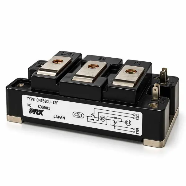
| Parameter |
Value |
| Manufacturer |
Powerex / Mitsubishi Electric |
| Part Number |
CM150DU-12F |
| Device Type |
Dual IGBT half-bridge with antiparallel super-fast diodes |
| Collector-Emitter Voltage (VCES) |
600 V |
| Continuous Collector Current (IC) |
150 A @ TC=25 °C |
| Pulse Collector Current |
300 A |
| Maximum Collector Dissipation |
Approximately 520 W @ TC=25 °C |
| VCE(sat) |
1.6 V typ. / 2.2 V max @ VGE=15 V, IC=150 A, 25 °C |
| Gate-Emitter Voltage (VGES) |
±20 V maximum |
| Gate Threshold VGE(th) |
5–7 V; approximately 6 V typical |
| Input Capacitance (Cies) |
Approximately 41 nF |
| Output Capacitance (Coes) |
Approximately 2.7 nF |
| Reverse Transfer Capacitance (Cres) |
Approximately 1.5 nF |
| Total Gate Charge (QG) |
Approximately 930 nC @ 300 V, 150 A, 15 V |
| Turn-On Delay |
Approximately 120 ns typical |
| Rise Time |
Approximately 100 ns typical |
| Turn-Off Delay |
Approximately 350 ns typical |
| Fall Time |
Approximately 250 ns typical |
| Free-Wheel Diode |
Super-fast antiparallel diode integrated with each IGBT |
| Diode Forward Voltage |
VEC up to approximately 2.6 V @ 150 A |
| Diode Reverse-Recovery Time |
Approximately 150 ns typical |
| Reverse-Recovery Charge |
Approximately 2.8 µC typical |
| Thermal Resistance, IGBT |
RthJC approximately 0.24 °C/W per IGBT |
| Thermal Resistance, Diode |
RthJC approximately 0.47 °C/W per diode |
| Case-to-Heatsink Thermal Resistance |
Approximately 0.07 °C/W with proper thermal interface |
| Isolation Voltage |
2.5 kV RMS / 1 minute, terminals-to-baseplate |
| Operating Junction Temperature |
−40 °C to +150 °C |
| Storage Temperature |
−40 °C to +125 °C |
| Terminal Torque |
M5 terminals approximately 2.5–3.5 N·m |
| Mounting Torque |
M6 mounting hardware approximately 3.5–4.5 N·m |
| Approximate Dimensions |
94 × 48 × 30 mm class |
| Approximate Weight |
310 g |
| Configuration |
Dual / 2-pack half-bridge |
| Condition |
Reclaimed Part |