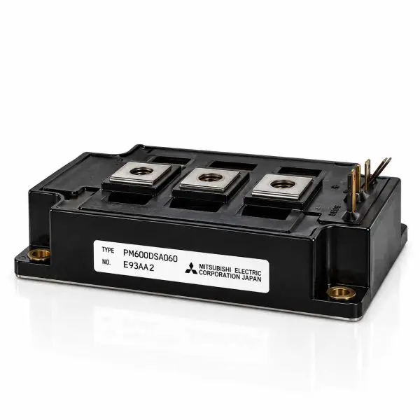
Mitsubishi Electric / Powerex — PM600DSA060 Intelligent Power Module
600 V • 600 A • Intelligent Power Module (IPM) • Dual IGBT Half-Bridge • Integrated Gate Drive & Protection • Isolated Baseplate • Reclaimed Part
What it is
The Mitsubishi Electric / Powerex PM600DSA060 is a high-current 600 V, 600 A Intelligent Power Module (IPM) that combines a dual IGBT half-bridge power stage, antiparallel fast-recovery diodes, optimized gate-drive circuitry, and integrated protection functions in a single industrial power module.
Unlike a conventional IGBT module that requires separate gate-driver and protection circuitry, the PM600DSA060 incorporates much of the critical switching control directly into the module. Integrated monitoring and protection functions include over-current, short-circuit, over-temperature, and control-supply under-voltage protection, helping protect both the semiconductor switches and the equipment in which the module is installed.
Its high-current dual-switch configuration forms a complete inverter leg suitable for UPS inverter stages, industrial power converters, servo and motion-control systems, high-power supplies, and other applications requiring fast switching and substantial current capability. The electrically isolated baseplate allows direct mounting to a heatsink while maintaining isolation between the power circuit and cooling assembly.
For legacy equipment, matching the complete PM600DSA060 part number is particularly important. An IPM replacement must match not only voltage, current, and mechanical dimensions, but also control-supply requirements, protection logic, fault outputs, control pinout, switching characteristics, and thermal performance.
At-a-Glance
- Manufacturer: Mitsubishi Electric / Powerex
- Part Number: PM600DSA060
- Voltage / Current: 600 V / 600 A
- Peak Current: Up to approximately 1200 A
- Module Type: Intelligent Power Module (IPM)
- Topology: Dual IGBT half-bridge with antiparallel diodes
- Gate Drive: Integrated
- Protection: Short-circuit, over-current, over-temperature and under-voltage
- Control Supply: 15 V nominal
- PWM Operation: Approximately 5–20 kHz recommended operating range
- Isolation: 2.5 kV RMS / 1 minute
- Mounting: Screw-mount with electrically isolated baseplate
- Use Cases: UPS systems; inverters; servo drives; motion control; industrial power supplies
- Condition: Reclaimed Part
Features
- Integrated intelligence — Combines high-power IGBTs, free-wheel diodes, gate-drive circuitry, monitoring, and protection in one module.
- High-current capability — 600 A operating class with substantial short-duration current capability.
- Low conduction loss — VCE(sat) approximately 1.8–1.9 V typical at rated current.
- Short-circuit protection — Integrated protection responds to abnormal high-current conditions.
- Over-current protection — Internal monitoring helps prevent destructive current levels.
- Over-temperature protection — Thermal protection helps protect the power semiconductor stage from excessive temperature.
- Under-voltage protection — Monitors the control/drive supply to prevent improper IGBT operation at insufficient gate-drive voltage.
- Fast free-wheel diodes — Integrated antiparallel diodes support efficient commutation in inverter and inductive-load applications.
- Isolated baseplate — Simplifies heatsink installation and electrical grounding strategy.
- Heavy-duty mechanical design — High-current M8 power terminals and robust mounting provisions for industrial equipment.
Technical Specifications
| Parameter |
Value |
| Manufacturer |
Mitsubishi Electric / Powerex |
| Part Number |
PM600DSA060 |
| Device Type |
Intelligent Power Module (IPM) |
| Power Configuration |
Dual IGBT half-bridge with antiparallel free-wheel diodes |
| Collector-Emitter Voltage (VCES) |
600 V |
| Collector Current (IC) |
600 A @ TC=25 °C |
| Peak Collector Current |
Approximately 1200 A |
| Collector Dissipation (PC) |
Approximately 1790 W |
| VCE(sat) |
Approximately 1.8–1.9 V typical / 2.6–2.7 V maximum at rated current, depending on temperature |
| Gate Drive |
Integrated gate-drive circuitry |
| Control Supply (VD) |
15 V nominal, approximately ±1.5 V operating tolerance |
| Over-Current Protection |
Integrated; approximately 740–1000 A trip range |
| Short-Circuit Protection |
Integrated; approximately 1000–1400 A trip range |
| Over-Temperature Protection |
Integrated; approximately 100–120 °C trip range |
| Under-Voltage Protection |
Integrated; approximately 11.5–12.5 V trip range |
| Recommended DC Bus |
Up to approximately 400 V under recommended operating conditions |
| Recommended PWM Frequency |
Approximately 5–20 kHz |
| Minimum Dead Time |
Approximately 3.5 µs |
| IGBT Thermal Resistance RthJC |
Approximately 0.07 °C/W |
| Diode Thermal Resistance RthJC |
Approximately 0.13 °C/W |
| Case-to-Heatsink Thermal Resistance |
Approximately 0.030 °C/W with suitable thermal compound |
| Isolation Test Voltage |
2500 V RMS / 1 minute, terminals-to-baseplate |
| Junction Temperature |
Approximately −20 °C to +150 °C |
| Case Temperature Range |
Approximately −20 °C to +100 °C |
| Storage Temperature |
Approximately −40 °C to +125 °C |
| Approximate Dimensions |
130 × 110 × 41 mm class |
| Approximate Mass |
910 g |
| Main Power Terminals |
M8 |
| Mounting Hardware |
M6 |
| Main Terminal Torque |
Approximately 8.83–10.8 N·m |
| Mounting Torque |
Approximately 1.96–2.94 N·m |
| Baseplate |
Electrically isolated flat base |
| Condition |
Reclaimed Part |
Compatibility / Representative Uses
| Module |
Representative Applications |
Replacement Notes |
| PM600DSA060 |
UPS inverter stages; industrial inverters; servo and motion-control equipment; motor drives; high-power industrial power supplies |
Confirm the exact PM600DSA060 part number, control pinout, 15 V drive supply, fault-output logic, dead-time requirements, mechanical footprint, terminal arrangement, and cooling requirements before substitution. |
Why Buy from Gruber
- Power electronics expertise — Experience supporting IGBT and intelligent power modules used in UPS, inverter, motor-drive, and critical-power equipment.
- Reclaimed legacy components — Hard-to-find Mitsubishi and Powerex modules for maintaining industrial equipment where original semiconductor assemblies may no longer be readily available.
- Tested components — Reclaimed IPMs can be evaluated for power-stage junction behavior, diode operation, continuity, isolation, and physical baseplate condition prior to resale.
- Traceability — Modules can be tracked through our service and inventory process for added replacement confidence.
- Replacement assistance — We can help compare the exact IPM variant, electrical ratings, control interface, protection functions, pinout, mounting footprint, and cooling requirements for legacy equipment repair.