Shop Products

Our Companies

Call Now For Support
1-800-658-5883

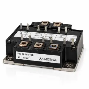
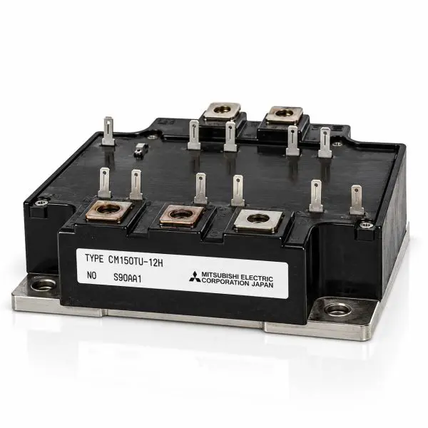
MITSUBISHI – CM150TU-12H – IGBT Power Module – 600V 150A Six-Pack 3-Phase Bridge – Reclaimed Part

Manufacturer

OEM Part Number

CM150TU_12H

GPS Part Number

27-MIT-CM150TU_12H

Tags

Price:

$136.00

Specifications
Voltage WPC AH/kVA Length Width Height Weight
600 V N/A 150 A N/A N/A N/A 680 g
Voltage 600 V
WPC N/A
Amp/H 150 A
Length N/A
Width N/A
Height N/A
Weight 680 g
Mitsubishi Electric — CM150TU-12H IGBT Power Module
600 V • 150 A • Six-Pack 3-Phase Bridge • 6 IGBTs + Antiparallel Free-Wheel Diodes • Isolated Baseplate • Reclaimed Part
What it is

The Mitsubishi Electric CM150TU-12H is a high-power 600 V, 150 A six-pack IGBT module containing the six switching devices required to form a complete three-phase inverter bridge. Each IGBT is paired with an antiparallel free-wheel diode, providing the current paths required for inductive loads in motor drives, UPS inverter stages, servo systems, welding equipment, and industrial power-conversion systems.

By integrating all three inverter legs into a single power module, the CM150TU-12H reduces the number of separate semiconductor packages, high-current bus connections, and heatsink mounting points required to construct a three-phase inverter. This makes it particularly useful when repairing legacy industrial equipment originally engineered around Mitsubishi’s six-pack IGBT architecture.

The module combines approximately 300 A pulsed collector-current capability with low saturation voltage, fast switching performance, and 2.5 kV RMS electrical isolation between the power circuit and baseplate. Its isolated mounting surface allows the module to be installed directly onto a properly prepared heatsink while maintaining electrical separation from the equipment chassis.

At-a-Glance
  • Manufacturer: Mitsubishi Electric
  • Part Number: CM150TU-12H
  • Voltage / Current: 600 V / 150 A
  • Peak Collector Current: Approximately 300 A pulsed
  • Topology: Six-pack / complete three-phase IGBT bridge
  • Semiconductors: 6 IGBTs with 6 antiparallel free-wheel diodes
  • Gate Rating: ±20 V maximum
  • Isolation: 2.5 kV RMS / 1 minute
  • Mounting: Screw-mount with isolated baseplate
  • Use Cases: UPS inverters; VFDs; AC motor drives; servo drives; welders; industrial power supplies
  • Condition: Reclaimed Part
Features
  • Complete three-phase bridge — Six IGBTs are integrated into a single module to provide three high-side and three low-side switching devices.
  • Integrated free-wheel diodes — Each switching position incorporates an antiparallel diode for handling inductive load current.
  • Low conduction loss — VCE(sat) approximately 2.4 V typical and 3.0 V maximum at 150 A and 25 °C.
  • Fast switching — Designed for efficient PWM inverter and motor-control applications with sub-microsecond switching characteristics.
  • Defined gate-drive characteristics — Typical total gate charge of approximately 300 nC under specified operating conditions.
  • High electrical isolation — 2.5 kV RMS terminal-to-baseplate isolation supports straightforward heatsink and chassis integration.
  • Efficient thermal design — Low junction-to-case thermal resistance supports high-current industrial operation when properly heatsinked.
  • Legacy equipment support — Useful for maintaining UPS, drive, servo, welding, and automation systems originally designed around this Mitsubishi module family.
Technical Specifications
Parameter Value
Manufacturer Mitsubishi Electric
Part Number CM150TU-12H
Device Type Six-pack IGBT module with antiparallel free-wheel diodes
Circuit Configuration Complete three-phase bridge — 6 IGBTs + 6 free-wheel diodes
Collector-Emitter Voltage (VCES) 600 V
Continuous Collector Current (IC) 150 A @ TC=25 °C
Peak Collector Current 300 A pulsed
Maximum Collector Dissipation (PC) 600 W under specified conditions
Gate-Emitter Voltage (VGES) ±20 V maximum
VCE(sat) @ 25 °C 2.4 V typical / 3.0 V maximum @ VGE=15 V, IC=150 A
VCE(sat) @ 125 °C Approximately 2.6 V typical
Gate Threshold Voltage (VGE(th)) 4.5–7.5 V; approximately 6 V typical
Total Gate Charge (QG) Approximately 300 nC @ VCC=300 V, IC=150 A, VGE=15 V
Input Capacitance (Cies) Approximately 13.2 nF
Output Capacitance (Coes) Approximately 7.2 nF
Reverse Transfer Capacitance (Cres) Approximately 2.0 nF
Turn-On Delay (td(on)) Approximately 100 ns typical
Rise Time (tr) Approximately 350 ns typical
Turn-Off Delay (td(off)) Approximately 300 ns typical
Fall Time (tf) Approximately 300 ns typical
Diode Reverse-Recovery Charge (Qrr) Approximately 0.36 µC @ IE=150 A, di/dt=−300 A/µs
IGBT Thermal Resistance RthJC Approximately 0.21 °C/W per transistor
Diode Thermal Resistance RthJC Approximately 0.47 °C/W per diode
Case-to-Heatsink Thermal Resistance Approximately 0.015 °C/W with thermal grease
Isolation Test Voltage 2.5 kV RMS / 1 minute, terminals-to-baseplate
Operating Junction Temperature −40 °C to +150 °C
Storage Temperature −40 °C to +125 °C
Terminal / Mounting Torque M5: approximately 2.5–3.5 N·m
Approximate Mass 680 g
Baseplate Electrically isolated metal baseplate
Configuration Three-phase six-pack bridge
Condition Reclaimed Part
Compatibility / Representative Uses
Module Representative Applications Replacement Notes
CM150TU-12H UPS inverter stages; variable-frequency drives; AC motor and servo drives; welding equipment; industrial power supplies; automation equipment Confirm the complete CM150TU-12H part number, six-pack circuit configuration, terminal arrangement, gate connections, mounting footprint, gate-drive requirements and heatsink interface before substitution.
Why Buy from Gruber
  • Power electronics expertise — Experience supporting UPS, inverter, motor-drive and critical-power equipment using high-power semiconductor modules.
  • Reclaimed legacy components — Hard-to-find Mitsubishi power modules for maintaining equipment where original semiconductor assemblies may no longer be readily available.
  • Traceability — Reclaimed modules can be tracked through our service and inventory process.
  • Replacement assistance — We can help compare voltage, current, circuit topology, gate-drive requirements, terminal layout and mechanical fit when replacing a legacy IGBT module.