Manufacturer
OEM Part Number
GPS Part Number
Categories
Tags
$177.00
| Voltage | WPC | AH/kVA | Length | Width | Height | Weight |
|---|---|---|---|---|---|---|
| 600 V | N/A | 100 A | N/A | N/A | N/A | 570 g |
| Voltage | 600 V |
| WPC | N/A |
| Amp/H | 100 A |
| Length | N/A |
| Width | N/A |
| Height | N/A |
| Weight | 570 g |
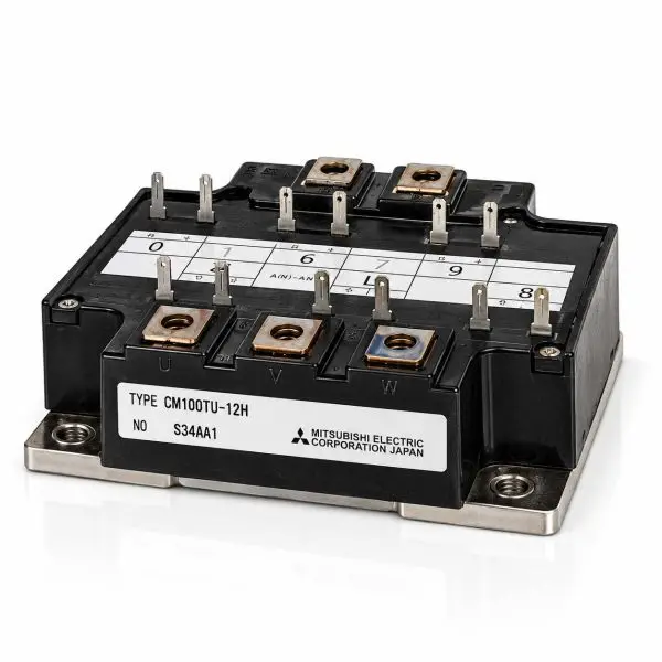
The Mitsubishi Electric CM100TU-12H is a high-power 600 V, 100 A six-pack IGBT module containing the six switching devices required to form a complete three-phase inverter bridge. Each IGBT is paired with an antiparallel free-wheel diode, allowing the module to handle the inductive currents encountered in motor drives, UPS inverter stages, servo systems, welding equipment, and industrial power-conversion systems.
Unlike single-switch and dual half-bridge modules that require several separate power blocks to construct a three-phase inverter, the CM100TU-12H integrates all three inverter legs into one isolated-base assembly. This reduces external bus connections, simplifies mechanical installation, and provides a compact replacement solution for equipment originally designed around Mitsubishi’s six-pack power-module architecture.
With a 600 V collector-emitter rating, 100 A continuous collector-current capability, approximately 200 A pulsed capability, and fast switching characteristics, the CM100TU-12H is designed for demanding industrial switching service. Its electrically isolated baseplate allows the module to mount directly to an appropriate heatsink while maintaining electrical isolation between the semiconductor circuit and chassis.
| Parameter | Value |
| Manufacturer | Mitsubishi Electric |
| Part Number | CM100TU-12H |
| Device Type | Six-pack IGBT power module with antiparallel diodes |
| Circuit Configuration | Complete three-phase bridge — 6 IGBTs + 6 free-wheel diodes |
| Collector-Emitter Voltage (VCES) | 600 V |
| Continuous Collector Current (IC) | 100 A |
| Peak Collector Current | Approximately 200 A pulsed |
| Gate-Emitter Voltage (VGES) | ±20 V maximum |
| VCE(sat) | 2.4 V typical / 3.0 V maximum @ VGE=15 V, IC=100 A, 25 °C |
| VCE(sat) at Elevated Temperature | Approximately 2.6 V typical @ 125 °C |
| Gate Threshold Voltage (VGE(th)) | 4.5–7.5 V; approximately 6 V typical |
| Total Gate Charge (QG) | Approximately 200 nC under specified switching conditions |
| Input Capacitance (Cies) | Approximately 8.8 nF |
| Output Capacitance (Coes) | Approximately 4.8 nF |
| Reverse Transfer Capacitance (Cres) | Approximately 1.3 nF |
| Turn-On Delay (td(on)) | Approximately 100 ns typical |
| Rise Time (tr) | Approximately 250 ns typical |
| Turn-Off Delay (td(off)) | Approximately 200 ns typical |
| Fall Time (tf) | Approximately 300 ns typical |
| Diode Reverse-Recovery Charge (Qrr) | Approximately 0.24 µC under specified test conditions |
| IGBT Thermal Resistance RthJC | Approximately 0.31 °C/W per transistor |
| Diode Thermal Resistance RthJC | Approximately 0.70 °C/W per diode |
| Maximum Collector Dissipation | Approximately 400 W per specified device conditions |
| Isolation Test Voltage | 2.5 kV RMS / 1 minute, terminals-to-baseplate |
| Terminal Torque | M4: approximately 1.3–1.7 N·m |
| Mounting Torque | M5: approximately 2.5–3.5 N·m |
| Approximate Mass | 570 g |
| Baseplate | Electrically isolated metal baseplate |
| Configuration | Three-phase six-pack bridge |
| Condition | Reclaimed Part |

| Module | Representative Applications | Replacement Notes |
| CM100TU-12H | UPS inverter stages; three-phase AC motor drives; variable-frequency drives; servo drives; welding equipment; laser power supplies; industrial automation and power-conversion equipment | Confirm the complete CM100TU-12H part number, six-pack circuit configuration, terminal arrangement, gate connections, mounting footprint, gate-drive requirements and heatsink interface before substitution. |