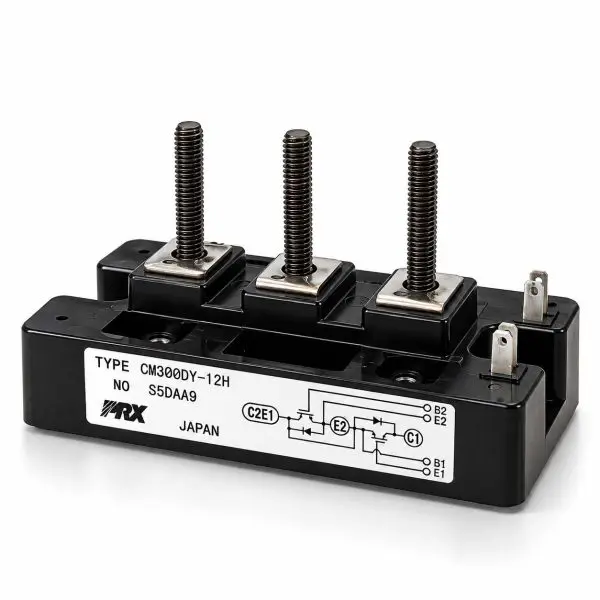
Powerex / Mitsubishi Electric — CM300DY-12H IGBT Power Module
600 V • 300 A • 600 A Pulsed • Dual IGBT Half-Bridge • Super-Fast Free-Wheel Diodes • Isolated Baseplate • Reclaimed Part
What it is
The Powerex CM300DY-12H is a high-current 600 V, 300 A dual IGBT power module configured as a two-transistor half-bridge. Each IGBT is paired with an antiparallel fast free-wheel diode, providing a complete high-power switching leg in a rugged industrial package with an electrically isolated baseplate.
Designed for demanding power-conversion equipment, the CM300DY-12H is well suited to UPS inverter and rectifier stages, industrial motor drives, variable-frequency drives, servo systems, DC choppers, welding equipment, and other high-current inverter applications. Its combination of high current capability, low saturation voltage, and fast diode recovery makes it particularly useful in equipment where switching efficiency and thermal performance are critical.
The dual half-bridge configuration places two matched IGBTs and their free-wheel diodes in one module, reducing external interconnections and simplifying inverter construction. The isolated baseplate allows the module to be mounted directly to a properly prepared heatsink while maintaining electrical isolation between the semiconductor circuit and chassis.
At-a-Glance
- Manufacturer: Powerex / Mitsubishi Electric
- Part Number: CM300DY-12H
- Voltage / Current: 600 V / 300 A
- Peak Current: Up to 600 A pulsed
- Topology: Dual IGBT half-bridge with antiparallel free-wheel diodes
- Mounting: Screw-mount with electrically isolated baseplate
- Gate Rating: ±20 V maximum VGE
- Isolation: 2.5 kV RMS / 1 minute
- Use Cases: UPS systems; industrial inverters; motor drives; servo systems; welding and high-power conversion
- Condition: Reclaimed Part
Features
- High-current capability — 300 A continuous collector-current rating with substantial short-duration pulsed-current capacity.
- Low conduction loss — Low VCE(sat) helps reduce semiconductor losses during high-current operation.
- Dual half-bridge construction — Two IGBTs in one package form a complete inverter switching leg.
- Fast commutation — Integrated super-fast free-wheel diodes support efficient switching of inductive loads.
- Wide safe operating area — Rugged power semiconductor construction for demanding hard-switched applications.
- ±20 V gate capability — Compatible with conventional industrial IGBT gate-drive architectures.
- Isolated baseplate — Simplifies heatsink installation and electrical isolation from the equipment chassis.
- Legacy equipment support — Useful for repair and maintenance of industrial equipment originally designed around Powerex/Mitsubishi IGBT modules.
Technical Specifications
| Parameter |
Value |
| Manufacturer |
Powerex / Mitsubishi Electric |
| Part Number |
CM300DY-12H |
| Device Type |
Dual IGBT half-bridge with antiparallel free-wheel diodes |
| Collector-Emitter Voltage (VCES) |
600 V |
| Continuous Collector Current (IC) |
300 A |
| Pulse Collector Current |
Up to approximately 600 A |
| Maximum Collector Dissipation |
Approximately 1.2 kW @ TC=25 °C |
| VCE(sat) |
Approximately 1.8–2.1 V typical / approximately 2.5 V max @ VGE=15 V, IC=300 A, 25 °C |
| Gate-Emitter Voltage (VGES) |
±20 V maximum |
| Gate Threshold VGE(th) |
Approximately 5–7 V; 6 V typical |
| Input Capacitance (Cies) |
Approximately 60–70 nF |
| Output Capacitance (Coes) |
Approximately 3 nF |
| Reverse Transfer Capacitance (Cres) |
Approximately 1.6 nF |
| Total Gate Charge |
Approximately 1000–1200 nC depending on test conditions |
| Free-Wheel Diodes |
Integrated antiparallel super-fast recovery diode for each IGBT |
| Diode Forward Voltage |
Approximately 2.2–2.8 V @ 300 A |
| Diode Reverse-Recovery Time |
Approximately 0.2–0.3 µs |
| Thermal Resistance — IGBT |
RthJC approximately 0.08–0.10 °C/W per IGBT |
| Thermal Resistance — Diode |
RthJC approximately 0.12–0.15 °C/W per diode |
| Isolation Voltage |
2.5 kV RMS / 1 minute, terminals-to-baseplate |
| Operating Junction Temperature |
−40 °C to +150 °C |
| Storage Temperature |
−40 °C to +125 °C |
| Package / Footprint |
Industrial dual IGBT screw-terminal module with isolated baseplate |
| Approximate Dimensions |
108 × 62 × 30 mm class |
| Approximate Weight |
500–600 g class |
| Typical Hardware Torque |
Approximately 4.5 N·m / 40 in-lb for applicable M6 hardware |
| Configuration |
Dual / 2-pack half-bridge |
| Condition |
Reclaimed Part |
Compatibility / Representative Uses
| Module |
Applications |
Replacement Notes |
| CM300DY-12H |
UPS inverter/rectifier bridges; industrial motor drives; VFDs; servo systems; DC choppers; welding and high-power industrial equipment |
Verify the complete CM300DY-12H part number, terminal and gate pinout, mounting footprint, bus voltage, gate-drive requirements, and thermal specifications before installation. |
Why Buy from Gruber
- Power electronics expertise — Experience supporting IGBT, SCR, diode, and power semiconductor modules used in UPS and industrial critical-power equipment.
- Hard-to-find legacy components — Reclaimed power modules can provide a practical repair path for equipment using obsolete or discontinued semiconductor assemblies.
- Tested reclaimed modules — Gate and diode behavior, semiconductor junctions, continuity, terminal condition, isolation, and baseplate condition can be evaluated prior to resale.
- Traceability — Modules can be tracked through our service and inventory process for additional replacement confidence.
- Replacement assistance — We can help compare electrical ratings, circuit configuration, mounting dimensions, terminal layout, gate-drive requirements, and thermal characteristics for legacy equipment repairs.