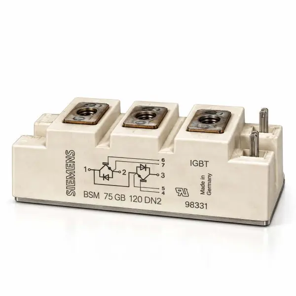
| Parameter |
Value |
| Manufacturer |
Siemens / EUPEC |
| Part Number |
BSM75GB120DN2 |
| Ordering Code |
C67076-A2106-A70 |
| Customer / Option Code |
BSM-75GB-120DN2-98331 — verify OEM option requirements before substitution |
| Device Type |
IGBT power module with integrated fast freewheeling diodes |
| Circuit Configuration |
Half-bridge |
| Collector-Emitter Voltage (VCE) |
1200 V |
| Collector-Gate Voltage (VCGR) |
1200 V @ RGE = 20 kΩ |
| DC Collector Current (IC) |
105 A @ TC = 25°C; 75 A @ TC = 80°C |
| Pulsed Collector Current (ICpuls) |
210 A @ TC = 25°C; 150 A @ TC = 80°C; tp = 1 ms |
| Gate-Emitter Voltage (VGE) |
±20 V |
| Power Dissipation per IGBT |
625 W @ TC = 25°C |
| Gate Threshold Voltage (VGE(th)) |
4.5 V min • 5.5 V typ • 6.5 V max |
| Collector-Emitter Saturation Voltage (VCE(sat)) |
2.5 V typ / 3.0 V max @ IC = 75 A, VGE = 15 V, Tj = 25°C |
| VCE(sat) @ 125°C |
3.1 V typ / 3.7 V max @ IC = 75 A, VGE = 15 V |
| Transconductance (gfs) |
31 S min @ VCE = 20 V, IC = 75 A |
| Input Capacitance (Ciss) |
5.5 nF typical |
| Output Capacitance (Coss) |
0.8 nF typical |
| Reverse Transfer Capacitance (Crss) |
0.3 nF typical |
| Turn-On Delay (td(on)) |
30 ns typ / 60 ns max @ VCC = 600 V, IC = 75 A, RG = 15 Ω |
| Rise Time (tr) |
70 ns typ / 140 ns max |
| Turn-Off Delay (td(off)) |
450 ns typ / 600 ns max |
| Fall Time (tf) |
70 ns typ / 100 ns max |
| Diode Forward Voltage (VF) |
2.3 V typ / 2.8 V max @ IF = 75 A, Tj = 25°C |
| Diode Reverse Recovery Time (trr) |
0.125 µs typical @ IF = 75 A, VR = −600 V, Tj = 125°C |
| Diode Reverse Recovery Charge (Qrr) |
3.2 µC typ @ 25°C • 12 µC typ @ 125°C |
| Thermal Resistance RthJC — IGBT |
≤ 0.20 K/W |
| Thermal Resistance RthJCD — Diode |
≤ 0.50 K/W |
| Isolation Voltage |
2500 V AC for 1 minute |
| Maximum Junction Temperature |
150°C |
| Storage Temperature |
−40°C to +125°C |
| Creepage Distance |
20 mm |
| Clearance |
11 mm |
| Baseplate |
Electrically insulated metal baseplate |
| Configuration |
IGBT half-bridge with integrated fast freewheeling diodes |