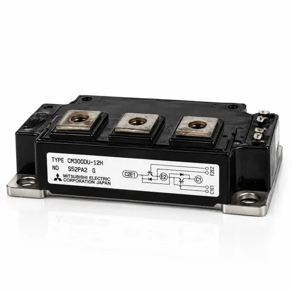
Mitsubishi Electric / Powerex — CM300DU-12H IGBT Power Module
600 V • 300 A • Dual IGBT Half-Bridge • 2 IGBTs + Antiparallel Fast Diodes • Isolated Baseplate • Reclaimed Part
What it is
The Mitsubishi Electric / Powerex CM300DU-12H is a high-current 600 V, 300 A dual IGBT power module containing two power IGBTs arranged as a half-bridge. Each switching device incorporates a reverse-connected fast free-wheel diode, providing the current paths required for efficient operation with inductive loads in inverter, motor-drive, UPS, and industrial power-conversion systems.
The two-device configuration provides a complete inverter leg in one rugged module, reducing external high-current interconnections and simplifying busbar, heatsink, and service design. Its isolated baseplate allows the module to be mounted directly to a properly prepared heatsink while maintaining electrical isolation between the semiconductor circuit and cooling surface.
With a 300 A continuous-current class rating and substantial short-duration current capability, the CM300DU-12H is suited to demanding UPS inverter and rectifier stages, variable-frequency drives, industrial motor controls, welding equipment, DC choppers, and other high-power switching applications. It is also valuable as a replacement component in legacy power electronics where the original Mitsubishi module must be matched for voltage, current, circuit configuration, gate drive, terminal arrangement, and mechanical footprint.
At-a-Glance
- Manufacturer: Mitsubishi Electric / Powerex
- Part Number: CM300DU-12H
- Voltage / Current: 600 V / 300 A
- Peak Collector Current: Approximately 600 A pulsed
- Topology: Dual IGBT half-bridge
- Semiconductors: 2 IGBTs with antiparallel fast free-wheel diodes
- Gate Rating: ±20 V maximum
- Isolation: 2.5 kV RMS / 1 minute
- Mounting: Screw-mount with isolated baseplate
- Use Cases: UPS systems; motor drives; industrial inverters; welders; high-power converters
- Condition: Reclaimed Part
Features
- High-current capability — 300 A continuous-current class with substantial pulsed-current capability for demanding power-conversion systems.
- Dual half-bridge design — Two IGBTs provide a complete inverter leg within a single module.
- Low conduction loss — Low VCE(sat) helps reduce semiconductor conduction losses under heavy load.
- Fast free-wheel diodes — Integrated antiparallel diodes support efficient commutation with inductive loads.
- Wide switching SOA — Designed for demanding inverter and motor-control switching environments.
- Rugged gate structure — ±20 V maximum gate-emitter rating supports standard industrial IGBT gate-drive systems.
- Isolated baseplate — Simplifies mounting to a common heatsink while maintaining electrical isolation.
- Legacy equipment support — Useful for maintaining UPS and industrial systems built around Mitsubishi dual IGBT power modules.
Technical Specifications
| Parameter |
Value |
| Manufacturer |
Mitsubishi Electric / Powerex |
| Part Number |
CM300DU-12H |
| Device Type |
Dual IGBT half-bridge with antiparallel fast diodes |
| Circuit Configuration |
Dual / 2-pack half-bridge |
| Collector-Emitter Voltage (VCES) |
600 V |
| Continuous Collector Current (IC) |
300 A @ TC=25 °C |
| Peak Collector Current |
Approximately 600 A pulsed |
| Maximum Collector Dissipation |
Approximately 1.2 kW @ TC=25 °C |
| VCE(sat) |
Approximately 1.8–2.1 V typical / approximately 2.5 V maximum @ VGE=15 V, IC=300 A, 25 °C |
| Gate-Emitter Voltage (VGES) |
±20 V maximum |
| Gate Threshold Voltage (VGE(th)) |
Approximately 5–7 V; approximately 6 V typical |
| Free-Wheel Diode Forward Voltage |
Approximately 2.2–2.8 V @ 300 A |
| Free-Wheel Diode |
Fast-recovery antiparallel diode integrated with each IGBT |
| IGBT Thermal Resistance RthJC |
Approximately 0.08–0.10 °C/W per IGBT |
| Diode Thermal Resistance RthJC |
Approximately 0.12–0.15 °C/W per diode |
| Isolation Test Voltage |
2.5 kV RMS / 1 minute, terminals-to-baseplate |
| Operating Junction Temperature |
−40 °C to +150 °C |
| Storage Temperature |
−40 °C to +125 °C |
| Approximate Dimensions |
108 × 62 × 30 mm class |
| Approximate Weight |
Approximately 500–600 g |
| Terminal / Mounting Torque |
Approximately 4.5 N·m (40 in-lb) for M6 hardware |
| Baseplate |
Electrically isolated metal baseplate |
| Configuration |
Dual IGBT half-bridge |
| Condition |
Reclaimed Part |
Compatibility / Representative Uses
| Module |
Representative Applications |
Replacement Notes |
| CM300DU-12H |
UPS inverter/rectifier bridges; variable-frequency drives; industrial motor controls; welding equipment; DC choppers; high-power industrial converters |
Confirm the complete CM300DU-12H part number, voltage and current ratings, terminal arrangement, gate-drive requirements, mechanical footprint, mounting hardware, and cooling requirements before substitution. |
Why Buy from Gruber
- Power electronics expertise — Experience supporting semiconductor modules used in UPS, inverter, motor-drive, and critical-power equipment.
- Reclaimed legacy components — Hard-to-find Mitsubishi and Powerex modules for maintaining equipment where original semiconductor assemblies may no longer be readily available.
- Tested components — Reclaimed modules can be inspected for semiconductor junction behavior, continuity, terminal condition, and baseplate condition prior to resale.
- Traceability — Modules can be tracked through our service and inventory process for added replacement confidence.
- Replacement assistance — We can help compare voltage, current, topology, gate-drive requirements, terminal layout, and mechanical fit when replacing a legacy IGBT module.