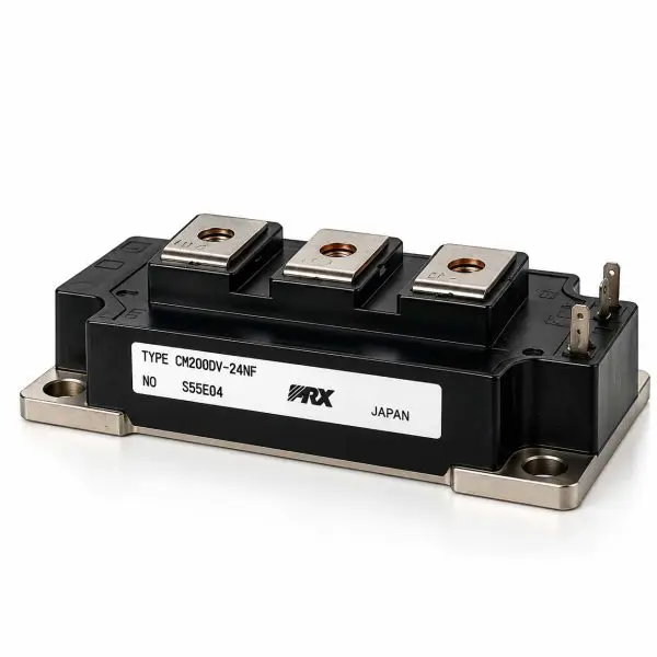
Powerex / Mitsubishi Electric — CM200DY-24NF IGBT Power Module
1200 V • 200 A • 400 A Pulsed • Dual IGBT Half-Bridge • Super-Fast Free-Wheel Diodes • Isolated Baseplate • Reclaimed Part
What it is
The Powerex CM200DY-24NF is a high-power 1200 V, 200 A dual IGBT module configured as a two-device half-bridge. Each IGBT is paired with an antiparallel fast free-wheel diode, providing a complete high-current switching leg in a rugged, electrically isolated power module.
Designed for demanding industrial power-conversion equipment, the CM200DY-24NF is commonly suited to UPS inverter and rectifier stages, industrial motor drives, variable-frequency drives, servo systems, DC-link converters, welding equipment, and other high-power inverter applications. Its 1200 V blocking capability provides substantial voltage headroom for high-voltage DC buses, while the 200 A current rating supports substantial continuous power handling.
The dual half-bridge configuration reduces component count when building inverter legs and provides closely matched power devices in a single package. An electrically isolated baseplate simplifies heatsink mounting and chassis integration, while the integrated free-wheel diodes provide the current path required when switching inductive loads such as motors, transformers, and inverter magnetics.
At-a-Glance
- Manufacturer: Powerex / Mitsubishi Electric
- Part Number: CM200DY-24NF
- Voltage / Current: 1200 V / 200 A
- Peak Current: Up to 400 A pulsed
- Topology: Dual IGBT half-bridge with antiparallel free-wheel diodes
- Mounting: Screw-mount with electrically isolated baseplate
- Gate Rating: ±20 V maximum VGE
- Isolation: 2.5 kV RMS / 1 minute
- Use Cases: UPS systems; industrial inverters; motor drives; servo systems; welding and high-power conversion
- Condition: Reclaimed Part
Features
- 1200 V blocking capability — Designed for high-voltage DC buses found in industrial inverters and critical-power systems.
- High-current operation — 200 A continuous collector-current rating with substantial pulsed-current capability.
- Dual half-bridge construction — Two IGBTs in one package provide a complete inverter switching leg.
- Low conduction loss — Low VCE(sat) helps control semiconductor losses during high-current operation.
- Fast commutation — Integrated antiparallel free-wheel diodes support efficient switching of inductive loads.
- Wide operating SOA — Rugged construction intended for demanding hard-switched power-conversion applications.
- Isolated baseplate — Simplifies heatsink installation, grounding, and electrical isolation from the equipment chassis.
- Service-friendly construction — Heavy-duty screw terminals and established industrial package format make the module well suited to legacy equipment repair.
Technical Specifications
| Parameter |
Value |
| Manufacturer |
Powerex / Mitsubishi Electric |
| Part Number |
CM200DY-24NF |
| Device Type |
Dual IGBT half-bridge with antiparallel free-wheel diodes |
| Collector-Emitter Voltage (VCES) |
1200 V |
| Continuous Collector Current (IC) |
200 A |
| Pulse Collector Current |
Up to approximately 400 A |
| Maximum Collector Dissipation |
Approximately 850–900 W @ TC=25 °C |
| VCE(sat) |
Approximately 1.8–1.9 V typical / approximately 2.4 V max @ VGE=15 V, IC=200 A, 25 °C |
| Gate-Emitter Voltage (VGES) |
±20 V maximum |
| Gate Threshold VGE(th) |
Approximately 5–7 V; 6 V typical |
| Input Capacitance (Cies) |
Approximately 60–80 nF |
| Output Capacitance (Coes) |
Approximately 3 nF |
| Reverse Transfer Capacitance (Cres) |
Approximately 1.6 nF |
| Total Gate Charge |
Approximately 1000–1200 nC depending on operating and test conditions |
| Free-Wheel Diodes |
Integrated antiparallel fast-recovery diode for each IGBT |
| Diode Forward Voltage |
Approximately 2.0–2.5 V @ 200 A |
| Diode Reverse-Recovery Time |
Approximately 0.2–0.3 µs |
| Thermal Resistance — IGBT |
RthJC approximately 0.10–0.12 °C/W per IGBT |
| Thermal Resistance — Diode |
RthJC approximately 0.15–0.18 °C/W per diode |
| Isolation Voltage |
2.5 kV RMS / 1 minute, terminals-to-baseplate |
| Operating Junction Temperature |
−40 °C to +150 °C |
| Storage Temperature |
−40 °C to +125 °C |
| Package / Footprint |
Industrial dual IGBT screw-terminal module with isolated baseplate |
| Approximate Dimensions |
108 × 62 × 30 mm class |
| Approximate Weight |
380–420 g |
| Typical Hardware Torque |
Approximately 4.5 N·m / 40 in-lb for applicable M6 hardware |
| Configuration |
Dual / 2-pack half-bridge |
| Condition |
Reclaimed Part |
Compatibility / Representative Uses
| Module |
Applications |
Replacement Notes |
| CM200DY-24NF |
UPS inverter/rectifier bridges; industrial motor drives; variable-frequency drives; servo systems; DC-link converters; welding and high-power industrial equipment |
Verify the complete CM200DY-24NF part number, terminal and gate pinout, mounting footprint, bus voltage, gate-drive requirements, and thermal specifications before installation. |
Why Buy from Gruber
- Power electronics expertise — Experience supporting IGBT, SCR, diode, and power semiconductor modules used in UPS and industrial critical-power equipment.
- Hard-to-find legacy components — Reclaimed power modules can provide a practical repair path for equipment using obsolete or discontinued semiconductor assemblies.
- Tested reclaimed modules — Gate and diode behavior, semiconductor junctions, continuity, terminal condition, isolation, and baseplate condition can be evaluated prior to resale.
- Traceability — Modules can be tracked through our service and inventory process for additional replacement confidence.
- Replacement assistance — We can help compare electrical ratings, circuit configuration, mounting dimensions, terminal layout, gate-drive requirements, and thermal characteristics for legacy equipment repairs.